Housing
WTI400 v1.2 — In service on the test vessel.
Overview
This section covers the WTI400 mechanical enclosure: the housing construction, ingress sealing, PCB mechanical specification, and fastening. The WTI400 is a self-contained NMEA 2000 device with power and data on a single Micro-C connector at one edge and the wind-transducer connection at the opposite edge.
Status: the housing design is not yet documented. The WTI400 V1.2 board is in service on the test vessel, but a formal enclosure selection, sealing scheme, and mechanical specification have not been captured in the evidence pipeline. The IP65 ingress rating and −10 °C to +70 °C operating temperature quoted on the product home page are design targets, not validated results — no enclosure has been qualified against them, and no IP-rated part has been selected and recorded. They are reproduced here only as design intent and must not be read as achieved figures.
The top faceplate decal artwork is defined, showing the connector layout as installed — the NMEA 2000 socket, the ESP-PROG header, the legacy serial connector, and the six-tab wind-transducer terminal block — with the product marking, compliance marks, and documentation QR code:

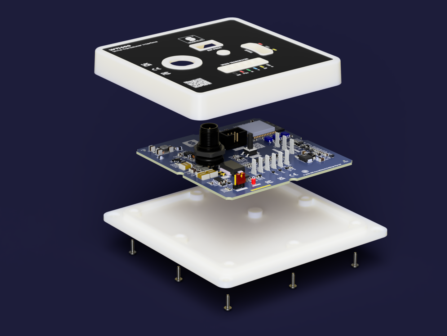
The exploded view shows the enclosure assembly stack — faceplate, housing shell, PCB, and rear:
The two facts below are confirmed from existing design records and are safe to state today; everything else is pending.
Full housing content is blocked until a housing design-intent record exists for the WTI400 V1.2 (the CANBench Duo housing precedent: a design-intent backfill is the precondition for authoring the mechanical pages). The following are still to be determined and documented:
- Enclosure selection — housing type, material, and part, including any extruded-aluminium or moulded option, and its orientation relative to the PCB.
- Sealing / IP rating validation — the gasket and sealing scheme, connector sealing when mated, internal pressure equalisation, and verification of the IP65 target by test.
- PCB mechanical — mounting-hole pattern, standoff scheme, and board-to-shell fixing.
- Fasteners — bezel-to-shell and PCB-to-shell fastening, screw types, and gasket-compression specification.
PCB outline
| Parameter | Value |
|---|---|
| Board dimensions | 95.2 × 95.2 mm |
| Layers | 4 |
| Surface finish | ENIG (immersion gold) |
| Solder mask | Dark blue |
| Fabrication class | IPC-6012 Class 2 |
The 95.2 × 95.2 mm four-layer outline is shared with the MDD400 sister product; the two boards use a common PCB outline and platform. Detailed board markings and reference-designator placement are documented on the Circuit Design — PCB markings page.
Connector edges
The WTI400 has connections on opposite edges of the board: power and NMEA 2000 data enter on a single Micro-C connector at one edge, and the wind transducer attaches at the opposite edge.
The V1.2 wind-transducer connection uses six Keystone 1211 quick-connect tabs. A panel-mount STA M12-S 6A IP67 6-pin connector is planned for V1.3 to replace the quick-connect tabs; the change to a sealed M12 connector is part of the path toward a qualified, sealed housing and is not present on V1.2.