WTI400 Overview
WTI400 v1.2 — In service on the test vessel. The board has accumulated approximately 1,000 sea miles running a simple PlatformIO/Arduino firmware that emits NMEA 2000 wind sentences with a self-calibrating ADC limits / midpoint scheme layered on top of hard-coded start-up constants. Wi-Fi has never been enabled on any WTI400 V1.2 board (on the in-service deployment or any other); BLE has only been exercised during early BLE-library development on test hardware. V1.2 evolved from the MLI400 V1.0 (Marine Legacy Interface), which carried a bespoke PlatformIO/Arduino wind-interface firmware through a global circumnavigation on the same test vessel. The next major project task is a production ESP-IDF firmware for V1.2, migrating the operational code paths from this predecessor.
Overview
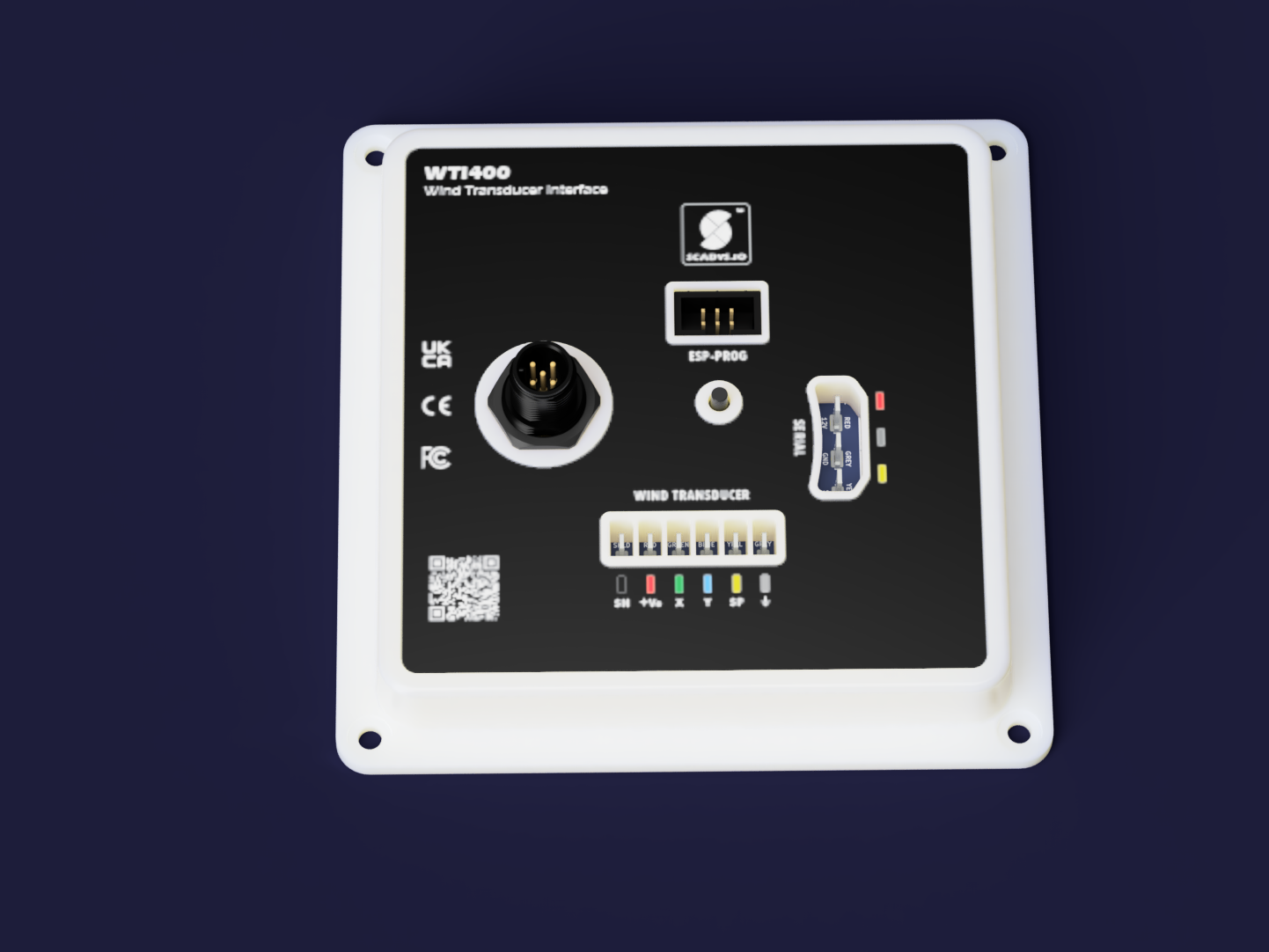
The WTI400 is a marine Wind Transducer Interface for NMEA 2000 networks. It connects directly to a standard analog sine-wave wind transducer at the masthead and outputs calibrated Apparent Wind Speed and Apparent Wind Angle as NMEA 2000 PGN 130306 messages on the vessel CAN bus. An onboard 6-DoF IMU (LSM6DSLTR) is fitted for heel / pitch / dynamic correction — to reference the wind output to the vessel's true horizon rather than the mast's instantaneous orientation — though this correction is not yet enabled in the current in-service firmware (see Firmware).
The WTI400 is a fully self-contained NMEA 2000 device: power and data enter on a single Micro-C connector, the wind transducer attaches at six quick-connect tabs on the opposite edge, and a single RGB LED + tactile button on the front face provide local UI without requiring a display.
Transducer compatibility is a defining characteristic of the WTI400. The board supports the Raymarine ST60 / E22078 / E22079 sine-wave family directly (JP1 8.4 V setpoint, V1.2). The B&G 213 is supply-compatible at the JP1 6.8 V setpoint but the V1.2 X / Y ADC bias is VCC-referenced rather than tracking the JP1 setpoint, clipping the negative half-cycle of the B&G 213 angle signal — full B&G 213 support is a V2.0 fix. See the Transducer Compatibility reference for the per-transducer pin-out, supply, and signal-level matrix.
The device is designed to launch at the Retail tier with the core wind-transducer monitoring feature set; legacy-serial bridging and the ESP-PROG programming socket are optional features present only on developer-facing tiers — see the feature matrix below.
Product tiers
The WTI400 follows the standard SCADYS.io Product Tiers model:
| Tier | Purpose | Compliance | Warranty | Assembly |
|---|---|---|---|---|
| Prototype | Engineering samples for selected testers / reviewers — V1.2 is at this tier today, in service on the test vessel | Not certified | None | Fully assembled |
| PCB Kit | PCB + SMT-populated, bring-your-own enclosure | Not certified | Limited | Customer mounts / finishes |
| Build Kit | Complete kit, customer-assembled | Not certified | Limited | Customer assembles |
| Retail | Fully assembled, tested, certified production unit | CE / UKCA / FCC / NMEA 2000 (target) | Standard consumer warranty | Factory-assembled |
The WTI400 V1.2 is currently a Prototype revision in service on the test vessel. The first Retail launch is expected to be a future revision (V1.3 or V2.0) once compliance testing and certification are complete, and the B&G 213 ADC fix lands — see the V1.3 / V2.0 backlog in the Tasks page.
Feature matrix
The WTI400 ships with a fixed core feature set on every tier and an optional feature set that varies by tier:
| Feature | Prototype | PCB Kit | Build Kit | Retail (launch) |
|---|---|---|---|---|
| Core features | ||||
| NMEA 2000 input + CAN transceiver | ✓ | ✓ | ✓ | ✓ |
| Wind-transducer connector (six quick-connect tabs; M12 6-pin in V1.3) | ✓ | ✓ | ✓ | ✓ |
| Dual-channel wind X / Y signal conditioning + ADC | ✓ | ✓ | ✓ | ✓ |
| Wind speed pulse conditioning (Schmitt trigger + firmware debounce) | ✓ | ✓ | ✓ | ✓ |
| LP2951 LDO wind-transducer supply (8.4 V / 6.8 V selectable via JP1) | ✓ | ✓ | ✓ | ✓ |
| 6-DoF IMU motion correction (LSM6DSLTR, heel / pitch / dynamic) | ✓ | ✓ | ✓ | ✓ |
| RGB LED + tactile button local UI | ✓ | ✓ | ✓ | ✓ |
| Wi-Fi + BT 5 LE configuration (ESP32-S3-WROOM-1, pre-certified module) | ✓ | ✓ | ✓ | ✓ |
| Marine sealed housing (target IP65) | ✓ | — (BYO) | ✓ | ✓ |
| Optional features | ||||
| Legacy serial interface (RX + TX, opto-isolated 12 V) | ✓ | ✓ | ✓ | — |
| ESP-PROG IDC socket (J1) + LDO programming chain | ✓ | ✓ | ✓ | — (pogo-pin) |
A ✓ means the feature is populated on that tier's bill of materials. A — means the corresponding components are DNP (do-not-populate) on that tier and the feature is not available.
Why the Retail tier launches without the optional features. Both optional features (legacy-serial 12 V opto-isolated bridge and the ESP-PROG programming socket with its developer-facing LDO chain) add components and certification scope without serving the core NMEA-2000-only use case. Retail launches with the smallest BOM that delivers the primary user experience; the optional features remain available on the Maker / Developer tiers (Prototype / PCB Kit / Build Kit) where the audience benefits from them. After the initial Retail launch, the legacy-serial path may return as a configurable extra cost option once the demand and compliance scope are characterised.
Specifications
| Parameter | Value |
|---|---|
| Power input | NMEA 2000 backbone, 9–16 V DC (Micro-C 5-pin connector) |
| Typical current draw (design target) | < 150 mA — ESP32 with Wi-Fi active, wind transducer powered, IMU polling at 52 Hz |
| Wind transducer support | Raymarine ST60 / E22078 / E22079 (JP1 8.4 V); B&G 213 supply-compatible at JP1 6.8 V (X/Y ADC fix in V2.0). See Transducer Compatibility |
| Wind transducer connector | Six Keystone 1211 quick-connect tabs (V1.2); STA M12-S 6A IP67 connector planned for V1.3 |
| Wireless | 2.4 GHz Wi-Fi 802.11 b/g/n, Bluetooth 5 LE (pre-certified module) |
| Motion sensor | STMicro LSM6DSLTR 6-DoF IMU (3-axis accelerometer + 3-axis gyroscope), I²C address 0x6A |
| Local UI | RGB LED (backlights the Scadys logo on the front face) + tactile button |
| Operating temperature | −10 °C to +70 °C (target — pending qualification) |
| PCB | 4-layer, 95.2 × 95.2 mm, ENIG, dark blue solder mask, IPC-6012 Class 2 — shared outline with MDD400 sister product |
| Compliance targets | EU RED 2014/53/EU (CE), UK Conformity Assessed (UKCA), FCC Part 15, RoHS, China EFUP, NMEA 2000 conformance |
| Compliance status (V1.2) | Designed-for; test reports pending V1.3 compliance pre-screening |
The typical current draw row is a design projection — Wi-Fi has not been enabled on any V1.2 board, so the contribution of the Wi-Fi radio has not been measured. The value will be validated during bench characterisation once the production firmware brings the radio up.
Operating heritage
The WTI400 V1.2 deployment on the test vessel has accumulated approximately 1,000 sea miles running a simple PlatformIO/Arduino firmware that emits NMEA 2000 PGN 130306 (apparent wind) at ~1 Hz. The firmware carries hard-coded start-up speed-conversion and installation-angle constants and hard-coded initial X / Y ADC limits; the limits and midpoint are self-adjusted at run-time as new extremes are observed. Wi-Fi has never been enabled on the in-service board (or any other WTI400 V1.2 board); BLE has only been exercised during early BLE-library development on test hardware. Both radios are in scope for the planned production ESP-IDF firmware.
The WTI400 V1.2 is the production-intent evolution of the MLI400 V1.0 (Marine Legacy Interface), a single-purpose wind interface that served the test vessel through a global circumnavigation. The MLI400 V1.0 ran a bespoke PlatformIO/Arduino firmware whose lineage feeds forward into the WTI400 V1.2 wind-processing code path and, ultimately, into the planned V1.2 production ESP-IDF firmware. The V1.2 hardware design improvements over the MLI400 — proper isolation domains, the force-commutated VCC bypass topology, the per-circuit GNDREF moats, and the on-board IMU that equips the design for horizon-referenced wind correction — are direct consequences of operating lessons from that circumnavigation. (That IMU-based correction is a design goal the hardware enables; it is not yet active in the current firmware — see Firmware.)
Version history
| Version | Status | Summary |
|---|---|---|
| v2.0 | Backlog — see Tasks | U12 amplifier-bias rework so V_bias tracks JP1 setpoint (enables native B&G 213 support); M12 wind-transducer connector; per-circuit GNDREF moats; longer-term redesigns |
| v1.3 | Backlog — see Tasks | Compliance pre-screening campaign; M12 6-pin wind connector; LP2951 DRG-package upgrade; ESP_EN routing shortening; I²C pull-up reduction for Fast mode; first Retail tier candidate |
| v1.2 | Current — in service on test vessel | First fabricated revision, in service on the test vessel for ~1,000 sea miles. Full nine-sub-sheet design: power supplies, CAN bus power, CAN transceiver, wind interface, ESP32 module, motion sensor, legacy serial RX/TX, button + LED, PCB markings |
| MLI400 v1.0 | Predecessor — retired | Marine Legacy Interface predecessor: single-purpose wind-interface device that served the test vessel through a global circumnavigation. Bespoke firmware lineage feeds forward into the WTI400 V1.2 |
Documentation map
| Section | What's there |
|---|---|
| User Manual | Operator guide — installation, calibration, daily use, fault-finding (in progress) |
| Quick Reference | Fast-lookup tables: pin assignments, power rails, external connectors, full component list, flash partitions |
| Transducer Compatibility | Per-transducer pin-outs, supply requirements, signal-level characteristics, and the V1.2 compatibility matrix (Raymarine / B&G) |
| Tasks | Live tracker for V1.2 in-service verification + the V1.3 / V2.0 backlog across hardware / firmware / housing / compliance |
| Circuit Design | Block diagram, four-domain ground map (GNDC / GNDREF / GND_WIND / GNDS), PCB stack-up, EMC philosophy, and a page per circuit |
| Compliance | CE / UKCA / FCC / RoHS / IP / NMEA 2000 conformance status and roadmap |
| Housing | Enclosure, sealing, PCB mechanical, and fasteners |
| Firmware | Current in-service firmware, the MLI400 V1.0 predecessor heritage, and the planned production ESP-IDF firmware |
Related products
- MDD400 — sister NMEA 2000 multi-function display node (shared PCB outline and platform); pairs with the WTI400 on the same backbone to show wind data at the helm.
- CANBench Duo — bench LISN + measurement fixture for NMEA 2000 device pre-compliance work.
- CANBench TrueZ — passive common-mode / differential-mode noise separator, companion to the CANBench Duo.