Housing
MDD400 v2.9 — Fabricated prototype — testing phase
Overview
This section covers the MDD400 mechanical enclosure: the housing construction, ingress sealing, PCB mechanical specification, and fastening. The MDD400 enclosure is designed for flush or surface mounting in cockpit and helm panel installations. It targets IP65 ingress protection — fully dust-tight and protected against water jets from any direction. The PCB is 95.2 × 95.2 mm (four-layer FR4, ENIG finish).
Status: v2.9 is a fabricated prototype in the testing phase; the figures below reflect the prototype design.
The rear faceplate decal shows the connector layout, status-LED window, product marking, compliance marks, and documentation QR code as they appear on the unit:

Enclosure
The exploded view shows the enclosure assembly stack — front bezel, display, PCB, and rear shell:
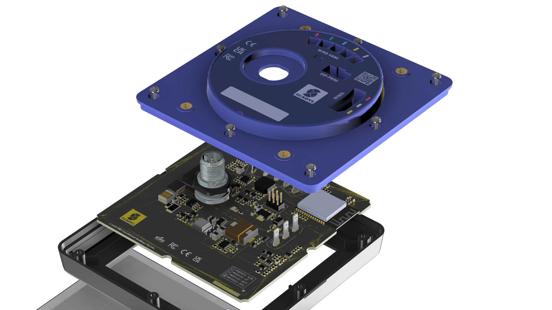
The housing consists of a front bezel, rear shell, and a perimeter gasket that seals the two halves together. The front surface is occupied by the DWIN 4.0-inch capacitive touchscreen. A clear window bonded to the bezel protects the display glass and provides the primary sealing surface on the front face.
Rear panel penetrations include the NMEA 2000 DeviceNet Micro-C connector (J1) and the Legacy Serial 3-pin Autohelm-style connector (J3). Both connectors are rated IP67 when mated. The USB programming port (J5) and the buzzer (BZ0, membrane-vented) are routed to the rear shell.
Sealing
| Feature | Target |
|---|---|
| Enclosure ingress protection | IP65 |
| Connector sealing (mated) | IP67 |
| Buzzer vent | Hydrophobic membrane |
Internal pressure equalisation is provided by a hydrophobic vent in the rear shell. This prevents condensation from pressure cycling in marine environments while maintaining the IP65 seal.
PCB Mechanical
| Parameter | Value |
|---|---|
| Board dimensions | 95.2 × 95.2 mm |
| Layers | 4 (signal / ground / power / signal) |
| Surface finish | ENIG (immersion gold) |
| Solder mask | Dark blue |
| Silkscreen | White, front and back |
Fasteners
The PCB is secured to the rear shell with M2 or M2.5 standoffs at the four corner mounting holes. The bezel and rear shell are held together with a perimeter of self-tapping screws into the shell bosses, compressing the gasket to the rated sealing force.