MDD400 Overview
MDD400 v2.9 — Fabricated prototype, bench-test phase. Each peripheral has been driven on the bench through dedicated hardware test routines (CAN / NMEA 2000 connectivity, the HMI display, the three I²C sensors, and the buzzer all individually functional). No production firmware has been written for V2.9 yet — the production ESP-IDF firmware is the next major project task, planned to migrate the operational code paths (tone library, alert taxonomy, brightness-control loop, three-tier thermal protection, NMEA 2000 PGN handling) from the MDD400 V1.0 PlatformIO/Arduino predecessor, which ran on earlier MDD400 hardware revisions through significant in-service operating hours including extended open-ocean passages. Wi-Fi has never been enabled on any MDD400 board, on any version; BLE has only been exercised during early BLE-library development on test hardware. Bringing both radios up in production form is part of the new firmware scope.
Overview
The MDD400 is a marine multi-function display node for NMEA 2000 vessel networks. It connects to a vessel's NMEA 2000 backbone with a single Micro-C connector — drawing power and receiving data from the bus — and presents the network data on a 4.0-inch high-contrast, sunlight-readable, wide-angle capacitive-touch TFT HMI display at the helm. It's a fully self-contained NMEA 2000 device: no external power, no auxiliary cabling, no separate display module.
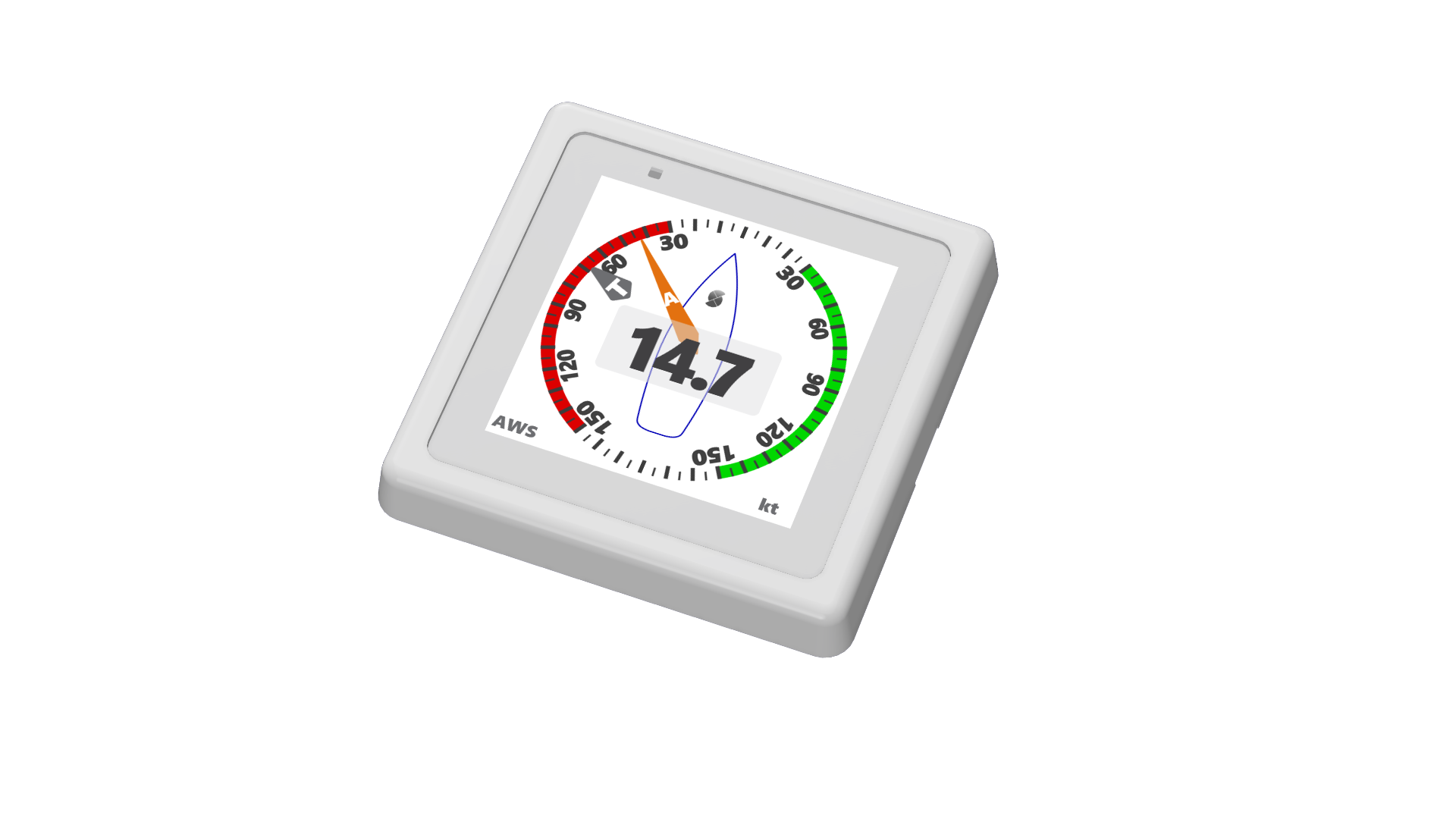
The MDD400 is intended for navigation / engine / environmental / alarm monitoring on cruising and passage-making yachts. Typical pages on the display include: power monitoring (bus voltage / current draw of the MDD400 itself), engine data (RPM, oil pressure, temperature), navigation (heading, speed over ground, depth), tank levels, wind data (when paired with a WTI400 or compatible wind interface on the same N2K backbone), and alarm conditions.
The device is designed to launch at the Retail tier with the core NMEA 2000 monitoring feature set; legacy-serial bridging and the ESP-PROG programming socket are optional features present only on developer-facing tiers — see the feature matrix below.
Product tiers
The MDD400 follows the standard SCADYS.io Product Tiers model:
| Tier | Purpose | Compliance | Warranty | Assembly |
|---|---|---|---|---|
| Prototype | Engineering samples for selected testers / reviewers — V2.9 is at this tier today | Not certified | None | Fully assembled |
| PCB Kit | PCB + SMT-populated, bring-your-own enclosure | Not certified | Limited | Customer mounts / finishes |
| Build Kit | Complete kit, customer-assembled | Not certified | Limited | Customer assembles |
| Retail | Fully assembled, tested, certified production unit | CE / UKCA / FCC / NMEA 2000 (target) | Standard consumer warranty | Factory-assembled |
The MDD400 V2.9 is currently a Prototype revision. The first Retail launch is expected to be a future revision (V2.10 or later) once compliance testing and certification are complete — see the V2.10 backlog in the Tasks page.
Feature matrix
The MDD400 ships with a fixed core feature set on every tier and an optional feature set that varies by tier:
| Feature | Prototype | PCB Kit | Build Kit | Retail (launch) |
|---|---|---|---|---|
| Core features | ||||
| NMEA 2000 input + CAN transceiver | ✓ | ✓ | ✓ | ✓ |
| 4.0″ high-contrast, sunlight-readable, wide-angle capacitive-touch TFT HMI display | ✓ | ✓ | ✓ | ✓ |
| Power monitor (INA219, NMEA 2000 bus voltage/current) | ✓ | ✓ | ✓ | ✓ |
| Ambient-light sensor (OPT3004, auto brightness) | ✓ | ✓ | ✓ | ✓ |
| Temperature sensor (TMP112, thermal protection) | ✓ | ✓ | ✓ | ✓ |
| Audio buzzer (MLT-8530, alert tones) | ✓ | ✓ | ✓ | ✓ |
| Service status LED (rear-facing — technician bring-up / fault-finding; DNP candidate in production) | ✓ | ✓ | ✓ | ✓ |
| Wi-Fi + BT 5 LE configuration (ESP32-S3-WROOM-1, pre-certified module) | ✓ | ✓ | ✓ | ✓ |
| Marine sealed housing (target IP65 front-of-helm) | ✓ | — (BYO) | ✓ | ✓ |
| Optional features | ||||
| Legacy serial interface (RX + TX, opto-isolated 12 V) | ✓ | ✓ | ✓ | — |
| ESP-PROG IDC socket (J1) + LDO programming chain | ✓ | ✓ | ✓ | — (pogo-pin) |
A ✓ means the feature is populated on that tier's bill of materials. A — means the corresponding components are DNP (do-not-populate) on that tier and the feature is not available.
Why the Retail tier launches without the optional features. Both optional features (legacy-serial 12-V opto-isolated bridge and the ESP-PROG programming socket with its developer-facing LDO chain) add components and certification scope without serving the core NMEA-2000-only use case. Retail launches with the smallest BOM that delivers the primary user experience; the optional features remain available on the Maker / Developer tiers (Prototype / PCB Kit / Build Kit) where the audience benefits from them. After the initial Retail launch, the legacy-serial path may return as a configurable extra cost option once the demand and compliance scope are characterised.
Specifications
| Parameter | Value |
|---|---|
| Power input | NMEA 2000 backbone, 9–16 V DC (Micro-C 5-pin connector) |
| Typical current draw (design target) | ~250 mA — display on, Wi-Fi active, all sensors polled at 1 Hz |
| Peak current draw (design target) | ~500 mA — display backlight 100 %, Wi-Fi TX burst |
| Display | 4.0″, 480 × 480, high-contrast, sunlight-readable, wide-angle capacitive-touch TFT HMI |
| Wireless | 2.4 GHz Wi-Fi 802.11 b/g/n, Bluetooth 5 LE (pre-certified module) |
| Sensors | INA219 power monitor (0x40), OPT3004 ambient light (0x44), TMP112 temperature (0x48) — all over a shared I²C Standard-mode bus |
| Audio | MLT-8530 passive electromagnetic transducer, 80 dB at 1 kHz |
| Operating temperature | −10 °C to +70 °C (target — pending qualification) |
| PCB | 4-layer, 95.2 × 95.2 mm, ENIG, dark blue solder mask, IPC-6012 Class 2 |
| Compliance targets | EU RED 2014/53/EU (CE), UK Conformity Assessed (UKCA), FCC Part 15, RoHS, China EFUP, NMEA 2000 conformance |
| Compliance status (V2.9) | Designed-for; test reports pending V2.10 compliance pre-screening |
The typical / peak current draw rows are design projections — Wi-Fi has not been enabled on any V2.9 board, so the contribution of the Wi-Fi radio under active and TX-burst conditions has not been measured. The values will be validated during bench characterisation once the production firmware brings the radio up.
Operating heritage
The MDD400 V2.9 currently runs only hardware test routines — no production firmware has been written for this revision. The next major project task is a production ESP-IDF firmware for V2.9, planned to migrate the operational code paths (HMI UI loop, ALS-driven brightness control, three-tier TMP112 thermal protection — alert → derate → graceful shutdown, buzzer alert taxonomy, NMEA 2000 PGN handling) from the MDD400 V1.0 PlatformIO/Arduino predecessor, which ran on earlier MDD400 hardware revisions through significant in-service operating hours including extended open-ocean passages on the test vessel. V2.9 introduces a new housing and a new ambient-light-sensor placement; the brightness lookup table will need to be re-calibrated against the V2.9 housing geometry before the migrated brightness loop can be deployed, but the underlying loop logic is proven on the V1.0 hardware.
Wi-Fi has never been enabled on any MDD400 board to date; bringing up the radio (Station mode, provisioning, OTA) is a fresh integration task within the production-firmware scope, not a port of existing behaviour. BLE has been exercised only during early BLE-library development on test hardware; a production BLE configuration service is similarly a fresh task. Both radios are in scope for the production ESP-IDF firmware.
Version history
| Version | Status | Summary |
|---|---|---|
| v2.10 | Backlog — see Tasks | Compliance pre-screening campaign; UART series damping; C37 dielectric confirmation; Display Interface and Buzzer Driver EMI scans; first Retail tier candidate |
| v2.9 | Current — bench-test phase | Ground-plane rework, CAN transceiver replaced (SN65HVD234DR), I²C isolator removed in favour of direct-bus topology, Legacy Serial TX transistor improvements, new housing and ALS placement |
| v2.8 | Archived | Preceded V2.9 ground-plane and CAN transceiver changes |
| v2.7 to v2.1 | Archived | Iterative improvements through pre-production engineering |
| v2.0 | Archived | First V2.x major revision |
| v1.0 | Archived | Initial production-intent design |
Documentation map
| Section | What's there |
|---|---|
| User Manual | Operator guide — setup, daily use, troubleshooting (in progress, pending production firmware) |
| Quick Reference | Fast-lookup tables: pin assignments, power rails, external connectors, full component list, flash partitions |
| Tasks | Live tracker for V2.9 verification + the V2.10 backlog across hardware / firmware / housing / compliance |
| Circuit Design | Block diagram, ground domain map, PCB stack-up, EMC philosophy, and a page per circuit |
| Compliance | CE / UKCA / FCC / RoHS / IP / NMEA 2000 conformance status and roadmap |
| Housing | Enclosure, sealing, PCB mechanical, and fasteners |
| Firmware | Current bench-test state, the MDD400 V1.0 predecessor heritage, and the planned production ESP-IDF firmware |
Related products
- WTI400 — wind transducer interface; pairs with the MDD400 on the same NMEA 2000 backbone to add apparent-wind data.
- CANBench Duo — bench LISN + measurement fixture for NMEA 2000 device pre-compliance work.
- CANBench TrueZ — passive common-mode / differential-mode noise separator, companion to the CANBench Duo.