CANBench TrueZ Overview
CANBench TrueZ v1.2 — Schematic-stage refresh of the V1.1 fabricated prototype. V1.2 is electrically identical to V1.1 and carries the InvenTree-canonical component metadata; no V1.2 boards exist yet — testing and bring-up reference the V1.1 hardware.
Other versions: v1.1 — fabricated prototype (current)
Overview
The CANBench TrueZ is a passive common-mode / differential-mode (CM/DM) noise separator for conducted-emissions diagnosis on DC-powered CAN-bus devices, including NMEA 2000 equipment. It takes the two RF line signals from a LISN and resolves them into their common-mode and differential-mode components, each presented on a 50 Ω SMA output for a spectrum analyser. Knowing the CM/DM split tells you which mitigation to reach for — a common-mode choke / ferrite, or differential filtering — instead of guessing.
TrueZ is the companion to the CANBench Duo DC LISN. The Duo provides the RF coupling, attenuation and front-end protection; TrueZ deliberately does only the mode separation and keeps everything else minimal. It is fully passive — no MCU, no firmware, no software — built from two 1:1 RF transformers and a small resistor/capacitor network implementing the Wang–Lee–Odendaal separator method.
Measurement workflow
TrueZ is the optional mode-separation stage of the conducted-emissions chain:
| Stage | Instrument | Role |
|---|---|---|
| Supply | Bench DC PSU | Clean regulated DC to the LISN |
| LISN | CANBench Duo | Filters the supply, taps RF disturbance on two 50 Ω SMA outputs (LISN+, LISN−) |
| Separation | CANBench TrueZ | Sums the two LISN lines for common-mode, differences them for differential-mode |
| Analyser | tinySA ULTRA (or equivalent) | Captures the CM or DM conducted-emissions spectrum |
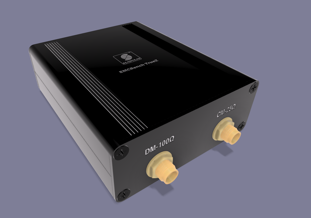
Drive the two TrueZ inputs from the Duo's LISN+ and LISN− measurement-port outputs using two identical SMA cables — cable matching matters, because skew between the two feeds converts DM↔CM and corrupts the separation. The two TrueZ outputs (CM-25Ω and DM-100Ω) connect, one at a time, to the analyser's 50 Ω input.
See the User Manual for the analyser setup and measurement procedure, the Quick Reference for the component list, and the Circuit Design section for the topology and rationale.
Operating envelope
The values below are design intent, calculated against the V1.2 topology (electrically identical to the fabricated V1.1); empirical confirmation via VNA / golden-prototype measurement is pending.
| Parameter | Value |
|---|---|
| Function | Passive CM/DM noise separator (Wang–Lee–Odendaal method) |
| Transformers | 2 × Mini-Circuits TC1-1-13M+, 1:1 (50 Ω) transmission-line baluns |
| Measurement band | 4.5 MHz – 3 GHz (transformer); useful from the low CISPR band up, with low-end correction |
| Low-frequency droop | Below ≈ 0.5 MHz — corrected with a one-time calibration curve |
| Inputs | LISN+, LISN− — two SMA jacks, 50 Ω, from the CANBench Duo LISN outputs |
| Outputs | CM-25Ω (49.9 Ω shunt ∥ analyser 50 Ω ≈ 25 Ω), DM-100Ω (49.9 Ω series + analyser 50 Ω) |
| Port impedance | 50 Ω at each SMA |
| Ground reference | J1 chassis banana (GNDREF) |
| Insertion loss (transformer) | ≈ 0.18 dB @4.5 MHz, ≈ 0.68 dB @1 GHz |
| Isolation floor | Set by transformer balance (0.5 dB amplitude, 2° phase typ) |
The CM-25Ω / DM-100Ω labels assume the analyser presents a 50 Ω input. A high-impedance scope input without a 50 Ω termination invalidates the intended loading and the calibration.
Scope and limitations
TrueZ is a pre-compliance / diagnostic fixture for engineering-level EMC work — identifying whether conducted noise is mainly common-mode or differential-mode and evaluating mitigations. It is not a certified laboratory reference instrument.
- Companion accessory, not standalone. TrueZ needs a LISN front end (the CANBench Duo) for the RF coupling, attenuation and protection it deliberately omits.
- Low-end accuracy needs correction. The TC1-1-13M+ droops below ≈ 0.5 MHz, so the bottom of the CISPR conducted band requires a correction curve; the production intent is a golden-prototype measurement.
- Not formally certified for CE / UKCA / RoHS at the V1.1 prototype stage — the marks are a forward-looking conformity claim on a RoHS basis (passive, non-powered accessory). See Compliance.
- Measurement geometry matters. Use matched cables and keep a repeatable setup during comparative measurements.
Version history
| Version | Status | Summary |
|---|---|---|
| v1.1 | Fabricated prototype | Sole built unit; pre-InvenTree legacy SCADYS symbol metadata. Testing and bench validation reference this hardware. |
| v1.2 | Next-version schematic | InvenTree symbol-library refresh; electrically identical to V1.1. No boards fabricated yet. |
Documentation map
| Section | What it covers |
|---|---|
| User Manual | Quick start, spectrum-analyser setup, measurement procedure, pitfalls, results interpretation |
| Quick Reference | BOM, connector roster |
| Circuit Design | CM/DM separator topology, connectors & markings, design rationale |
| Housing | Yongu H06 extruded-aluminium enclosure, assembly |
| Compliance | Regulatory markings, certification status |
| Tasks | Calibration measurement, marking fixes, validation outstanding |
The CANBench TrueZ is fully passive — no microcontroller, no firmware, no software of any kind. There is intentionally no Firmware section.
Related products
- CANBench Duo — the dual-line DC LISN that feeds TrueZ. TrueZ connects between the Duo's two LISN outputs and a single analyser input.
- MDD400, WTI400, MLI400, MDG400 — SCADYS-IO marine electronics whose conducted emissions can be characterised with the Duo + TrueZ chain.