Housing
CANBench TrueZ v1.1 — Fabricated prototype, sole built unit. V1.1 is electrically identical to the V1.2 schematic refresh but predates the InvenTree symbol-library migration; the schematic component metadata reflects legacy SCADYS naming. Testing and bench validation reference this V1.1 hardware.
Other versions: v1.2 — schematic refresh (next version)
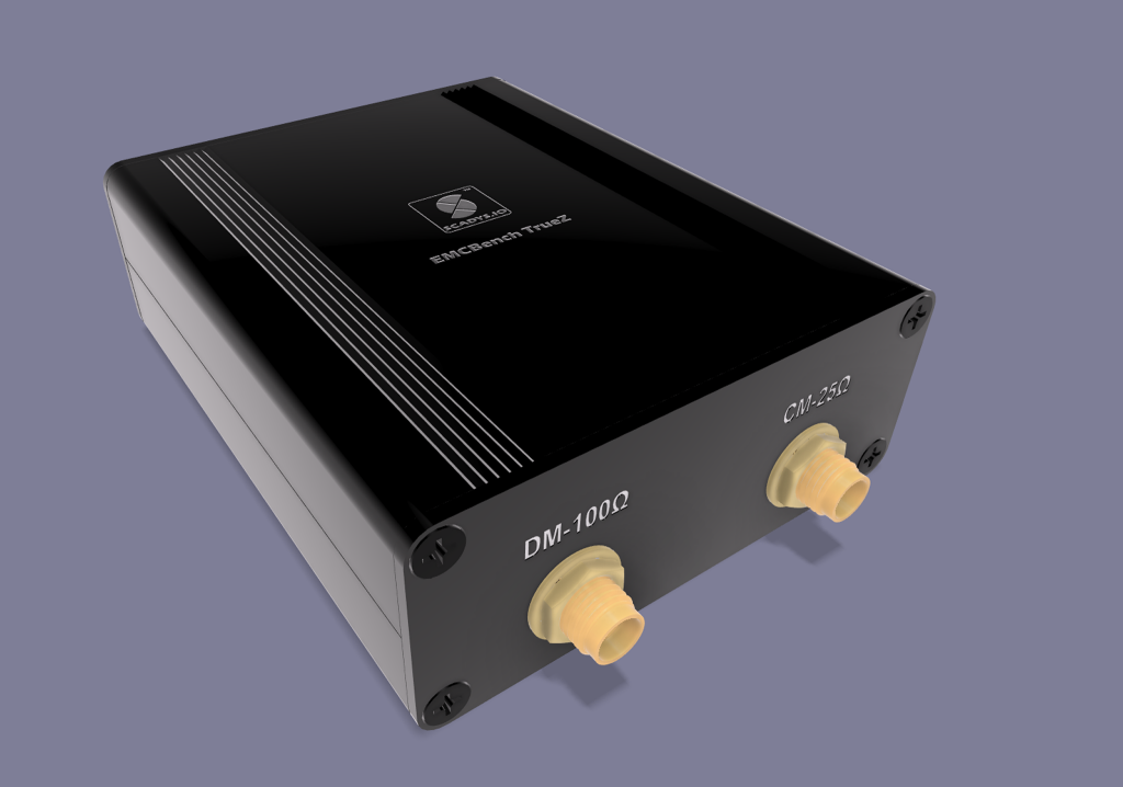
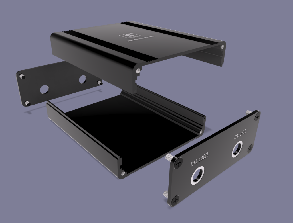
The CANBench TrueZ is housed in a Yongu H06 split extruded-aluminium enclosure — a small two-piece extrusion with a slide-in PCB and screwed end plates (faceplates).
Overview
This page covers the mechanical housing of the CANBench TrueZ — a passive measurement instrument with no active electronics. It documents the enclosure (Yongu YG-H06), the faceplate layout and markings, chassis bonding, and the build-order assembly sequence used for the fabricated prototype.
Status: the V1.1 unit is the sole fabricated prototype. Dimensions are a working spec from the design record and the Yongu YG-H06 manufacturer drawing; the marking artwork carries pre-production placeholders.
Enclosure
| Parameter | Value |
|---|---|
| Type | Yongu H06 split extruded aluminium |
| Body width | 63 mm |
| Body height | 25 mm |
| Internal slide length | 75 ± 0.1 mm |
| Body material | 6063-T5 extruded aluminium |
| End plates | 5052-H32 aluminium |
| Fixings | M2.5 × 6 countersunk screws |
| Finish | Black anodized, laser-etched labels |
The PCB outline is 71 × 42 mm and slides lengthwise into the 75 mm internal channel. The PCB plus its SMA flanges is ≈ 0.35 mm shorter than the internal length, which drives the assembly sequence below (avoid pre-stressing the faceplates).
Faceplate & markings
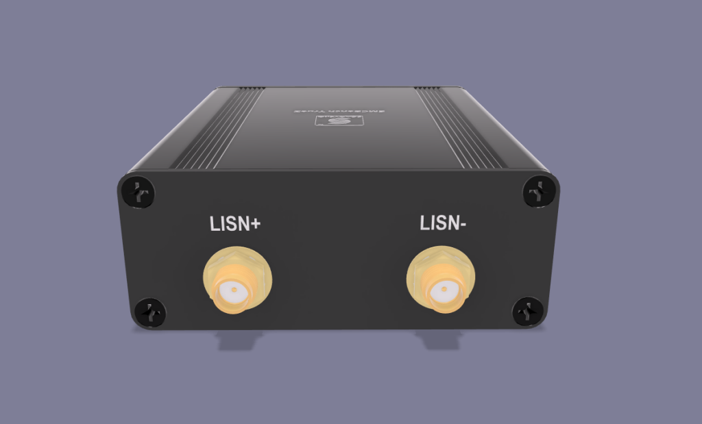
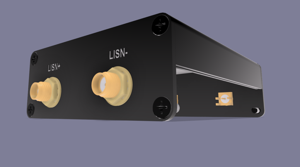
- Input faceplate:
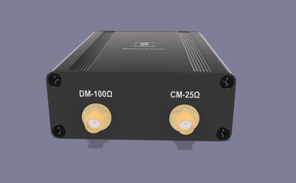
LISN+/LISN−(SMA). - Output faceplate:
DM-100Ω/CM-25Ω(SMA). - Bottom: product label, documentation QR code, product-code barcode, compliance marks.
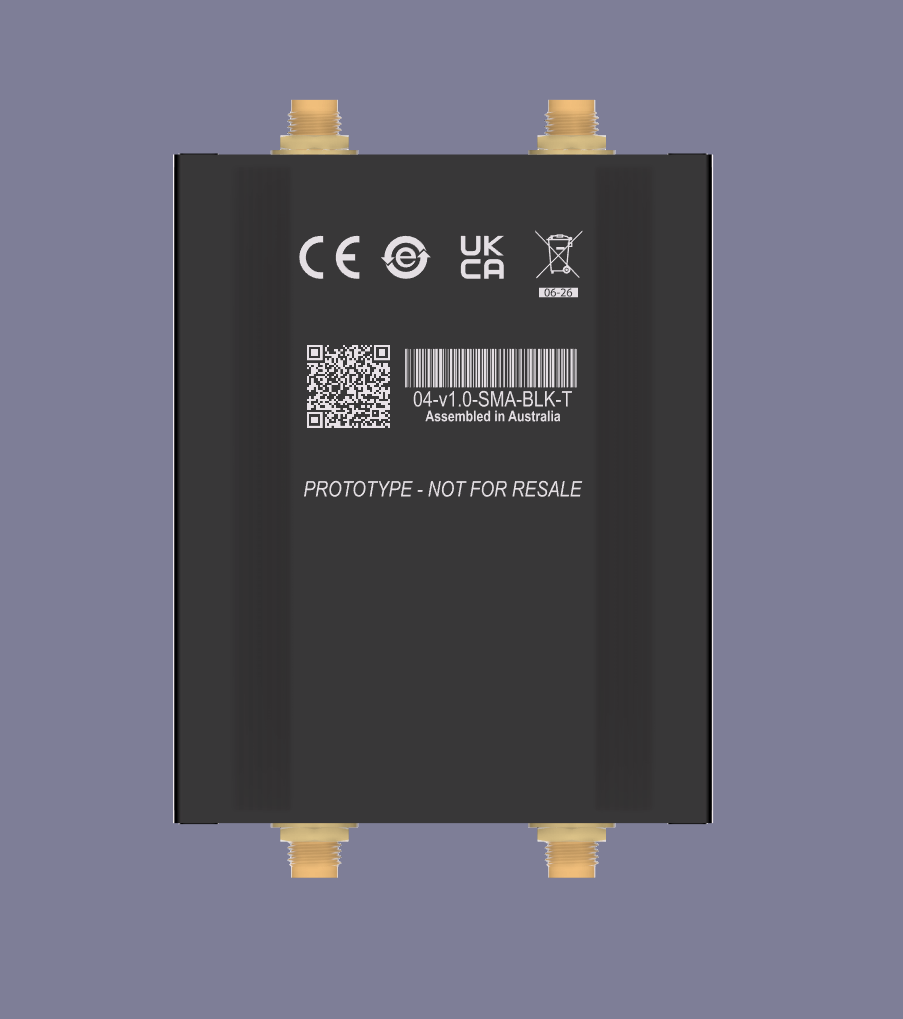
The QR code and product/version code in the current artwork are pre-production placeholders to be corrected before production release — see Tasks.
Chassis bonding
The SMA shells and mounting hardware bond the PCB GNDREF copper to the aluminium chassis, stabilising the RF return paths and improving measurement repeatability — consistent with the single-GNDREF EMC philosophy of the Circuit Design.
Assembly sequence
The SMAs are soldered in place (rather than pre-soldered then forced into the enclosure) to avoid residual stress and faceplate bending given the ~0.35 mm length clearance.
-
Disassemble the enclosure.
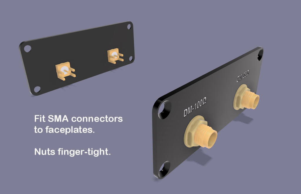
-
Fit the SMA connectors to the faceplates, nuts finger-tight only, noting SMA pin orientation.
-
Fit the faceplates to the top extrusion, again noting SMA pin orientation.
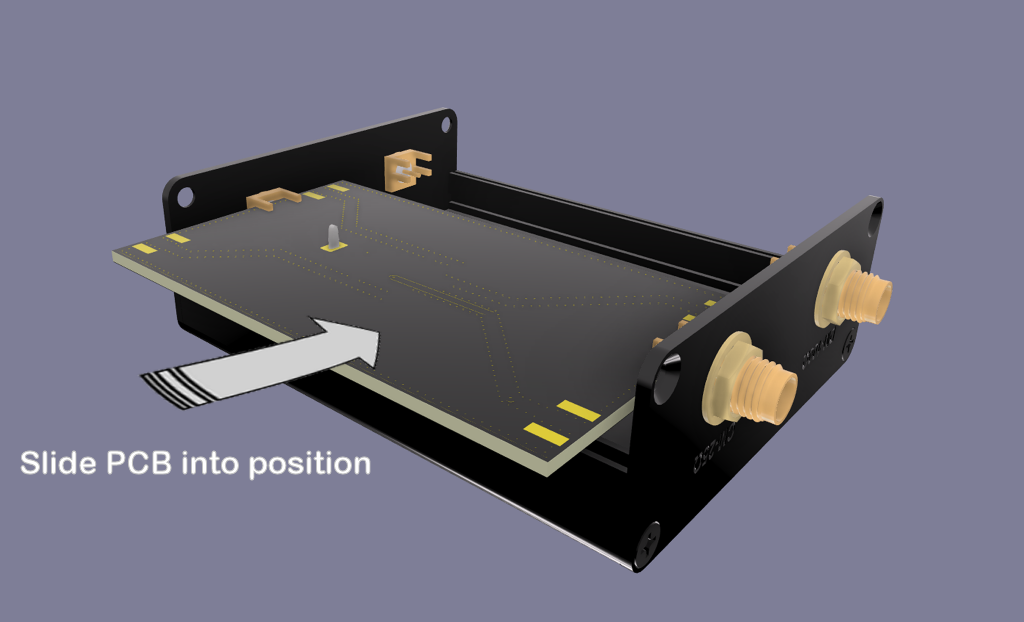
-
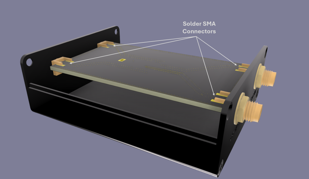
Slide the PCB into position between the SMA pins.
-
Solder the SMA ground pins to the bottom of the PCB.
-
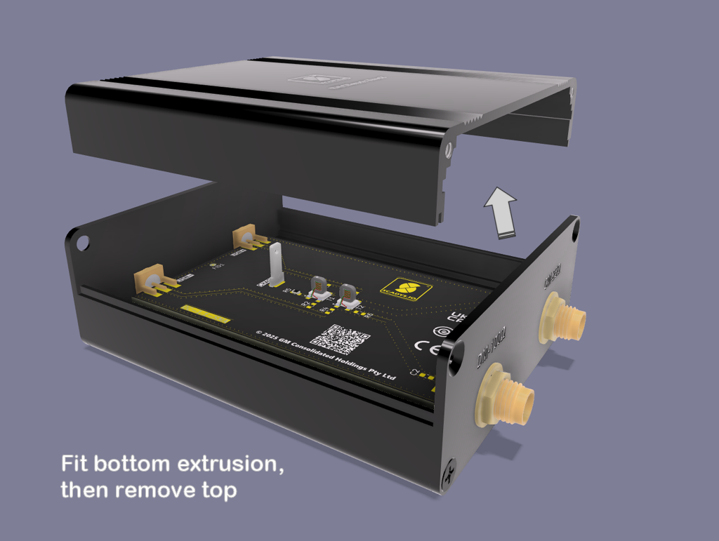
Fit the bottom extrusion, then remove the top extrusion.
-
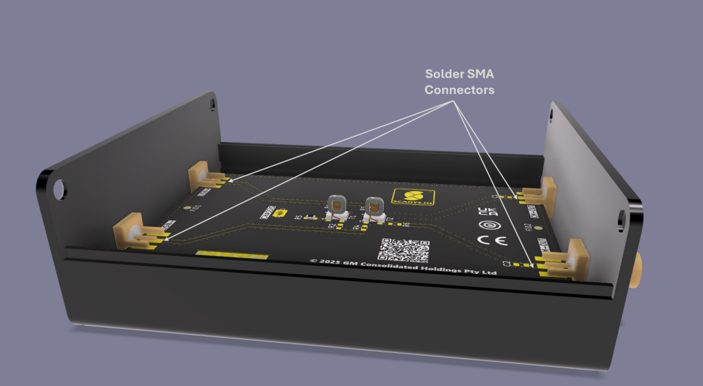
Solder the SMA top pins.
-
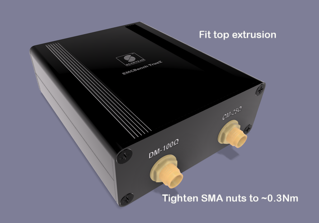
Reassemble the top extrusion and tighten the SMA nuts to ≈ 0.3 N·m.
Notes
No IP rating is specified — this is a bench accessory, not an environmental enclosure.
Gaps & next version
- Dimensions are a working spec from the design record and the Yongu YG-H06 manufacturer drawing; confirm against the drawing and the as-built unit before production.
- The QR code and product/version code in the current marking artwork are pre-production placeholders to be corrected before production release — see Tasks.
Related pages
- Circuit Design — single-GNDREF EMC philosophy behind the chassis bond
- Connectors (Quick Reference) — SMA port assignments
- Tasks — outstanding pre-production items
References
- Yongu YG-H06 split extruded-aluminium enclosure — manufacturer drawing
- CANBench TrueZ design record (working mechanical spec)