CANBench Duo Overview
CANBench Duo v1.2 — Schematic-stage refresh of the V1.1 fabricated prototype. V1.2 is electrically identical to V1.1 and carries the InvenTree-canonical component metadata; no V1.2 boards exist yet — testing and bring-up reference the V1.1 hardware.
Other versions: v1.1 — fabricated prototype (current)
Overview
The CANBench Duo is a dual-line DC LISN (Line Impedance Stabilisation Network) with an integrated CAN common-mode monitor. It supports conducted-emissions measurement on CAN-bus and similar low-voltage DC supply pairs, from 150 kHz to 108 MHz, per the CISPR 25 measurement band.
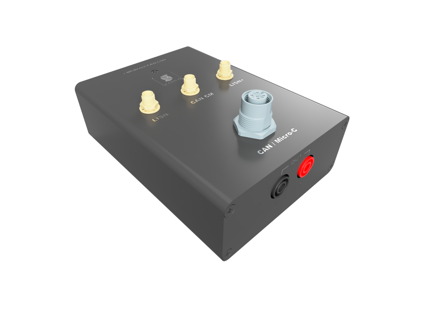
The instrument is passive — no MCU, no firmware, no switching converter. A bench DC supply enters through the front faceplate banana sockets, passes through reverse-polarity protection, a ferrite + 5 µH LC ladder filter, and emerges at the back faceplate to power the device under test. Three SMA outputs on the top extrusion present 50 Ω measurement taps: one for each LISN rail (LISN+ and LISN−), plus a common-mode tap on the CAN bus lines.
Measurement workflow
The CANBench Duo is the input stage of a three-instrument measurement chain:
| Stage | Instrument | Role |
|---|---|---|
| Supply | Bench DC PSU | Clean regulated 9–48 V supply to the LISN |
| LISN | CANBench Duo | Filters the supply, taps RF disturbance via 50 Ω SMA outputs |
| Optional | CANBench TrueZ | Separates Common-Mode (CM) and Differential-Mode (DM) RF components from the dual LISN outputs |
| Analyser | tinySA ULTRA (or equivalent) | Captures the conducted-emissions spectrum from 150 kHz upward |
The DUT plugs into the back-faceplate banana pair (or via the M12 N2K connector for combined supply + CAN). The user reads conducted-emissions signatures off the spectrum analyser while the DUT operates normally.
See the User Manual for the spectrum-analyser configuration and the measurement procedure, and the Quick Reference for the full component list. The Circuit Design section walks through each functional block.
Operating envelope
The values below are design intent. They have been calculated from V1.2 datasheet specs against the V1.1 fabricated topology; empirical confirmation via thermal and VNA testing is pending.
| Parameter | Value |
|---|---|
| Supply voltage range | 9–48 V continuous DC |
| Continuous current | 4.0 A @ 25 °C ambient (3.0 A @ 40 °C ambient) |
| Short surge current | 10 A for ≤ 10 ms, 6 A for ≤ 100 ms |
| Measurement band | 150 kHz – 108 MHz (CISPR 25), with margin to 120 MHz |
| LISN port impedance | ≈ 4.7 Ω at 150 kHz, rising as jωL for a 5 µH ladder |
| RF output impedance | 50 Ω at each SMA |
| Analyser-side residual transient limit | ≤ +10 dBm into 50 Ω |
| ESD tolerance at SMA | IEC 61000-4-2 ±8 kV air, ±6 kV contact (topological design target; component-level rating subject to TVS datasheet) |
| Reverse-polarity protection | Yes — self-biased ideal-diode MOSFET pair, +RED LED indicator |
| Fuse | 5 A Littelfuse Nano2 Slo-Blo on the SRC+ rail |
Scope and limitations
The CANBench Duo is intended for conducted-emissions measurement at the engineering-validation level — comparing prototype designs, characterising EMI signatures, finding noise sources during product development. The CISPR 25 5 µH artificial-network topology and the 10 dB measurement-port attenuation match the standard's setup; the instrument itself is not a certified compliance test fixture.
- Not for ISO 7637-2 transient testing. The protection chain handles ESD and bench-mishap events. ISO 7637-2 Pulse 5a/5b (load dump, 100+ V sustained transients) would exceed the MOSFET protection chain's voltage rating.
- Not formally certified for CE / UKCA / RoHS at the V1.1 prototype stage. The PCB silkscreen carries the regulatory marks as a forward-looking conformity claim; formal Declaration of Conformity and EMC test reports are pending.
- Measurement geometry matters. Low-level common-mode measurements are sensitive to cable routing, nearby electronics, and ground coupling — maintain repeatable geometry during comparative tests. See the User Manual → Common Pitfalls page for environmental-coupling guidance.
Version history
| Version | Status | Summary |
|---|---|---|
| v1.1 | Fabricated prototype | Sole built unit. Pre-InvenTree legacy SCADYS symbol metadata. Reference hardware for testing and bench validation. |
| v1.2 | Schematic refresh | InvenTree-canonical component metadata. Electrically identical to V1.1; no boards fabricated. |
Documentation map
| Section | What it covers |
|---|---|
| User Manual | Quick start, spectrum-analyser setup, measurement procedure, status LED, pitfalls, results interpretation |
| Quick Reference | BOM, connector roster, LED state lookup |
| Circuit Design | Per-block schematic, topology, and design rationale |
| Housing | YG-H10A extruded aluminium enclosure, cable routing |
| Compliance | Regulatory markings, certification status |
| Tasks | V1.3 fixes planned, validation work outstanding |
The CANBench Duo is fully passive — no microcontroller, no firmware, no software of any kind. There is intentionally no Firmware section.
Related products
- MDD400, WTI400, MLI400, MDG400 — SCADYS-IO marine electronics that share the M12 N2K connector pinout. Any of these can be powered + bussed via the CANBench Duo's M12 (J10) connector.
- CANBench TrueZ — CM/DM RF separator. Connects between the CANBench Duo's two LISN outputs (
LISN+andLISN−) and a single spectrum-analyser input, separating the dual-rail signature into common-mode and differential-mode components. Available as a separate SCADYS-IO product.